Read IMU raw data
Read IMU raw data1.IMU Introduction2.IMU principle3.Brief analysis of IMU driver codeExperimental effect
1.IMU Introduction
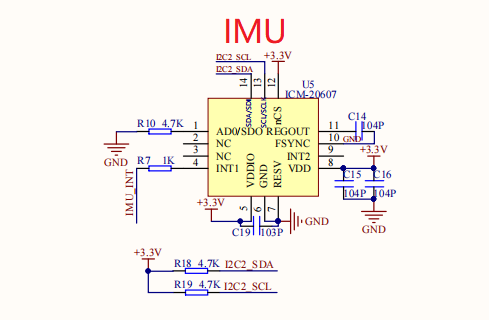
The IMU used on the board is the ICM-20607 model, which is the upgraded version of MPU6050. However, compared with MPU6050, it lacks the function of four-element conversion of Euler angle. You need to write this part of function yourself. This tutorial does not provide the functions of this part. Interested students can learn from CSDN by themselves. ICM-20607: gyroscope included in it is used to measure angular velocity; Accelerometer, used to measure linear velocity.
2.IMU principle
According to the manual and schematic diagram
 The following results can be obtained:
- IMU can be controlled by I2C protocol or SPI protocol, but the schematic diagram shows that it can only be controlled by I2C, and this experiment uses the communication mode of software I2C.
- The accelerometers and gyroscopes of the IMU on board are set with corresponding ranges through register configuration.
- The I2C address of IMU is related to the level of AD0 pin. The address of AD0=0: I2C is 0x68, and the address of AD0=1: I2C is 0x69
3.Brief analysis of IMU driver code
x//initvoid icm20607_init(void){ uint8_t val = 0x0; IIC_Init(); delay_ms(10); icm20607_who_am_i(); icm_i2c_write(PWR_MGMT_1, 0x80); //Reset device delay_ms(100); icm20607_who_am_i(); do { //Wait for the reset to succeed icm_i2c_read(PWR_MGMT_1, &val, 1); } while(0x41 != val); icm_i2c_write(PWR_MGMT_1, 0x01); //Clock setting icm_i2c_write(PWR_MGMT_2, 0x00); //Turn on gyroscope and accelerometer icm_i2c_write(CONFIG, 0x01); //176HZ 1KHZ 0x01 icm_i2c_write(SMPLRT_DIV, 0x07); // SAMPLE_RATE = INTERNAL_SAMPLE_RATE / (1 + SMPLRT_DIV) 0X07 icm_i2c_write(GYRO_CONFIG, 0x18); //±2000 dps// icm_i2c_write(GYRO_CONFIG, 0x08); //±500 dps icm_i2c_write(ACCEL_CONFIG, 0x10); //±8g// icm_i2c_write(ACCEL_CONFIG, 0x00); // ±2 icm_i2c_write(ACCEL_CONFIG_2, 0x23); }It can be seen from the initialization function that the I2C interface of the communication is initialized first, and then the IMU is detected whether it is online, and its register is initialized when it is online
When the initialization is successful, enter the data reading
xxxxxxxxxx// Get the attitude angle of gyroscopevoid get_icm_attitude(void){ char bnb[20]; if (icm_check_time < ICM_SKIP) { icm_check_time++; icm_update_data(); DEBUG("icm_check:%d, x:%d, y:%d, z:%d\n", icm_check_time, icm_gyro_x, icm_gyro_y, icm_gyro_z); if (icm_check_time <= ICM_ABANDON) return; Deviation_gyro[0] += icm_gyro_x; Deviation_gyro[1] += icm_gyro_y; Deviation_gyro[2] += icm_gyro_z; Deviation_acc[0] += icm_acc_x; Deviation_acc[1] += icm_acc_y; Deviation_acc[2] += icm_acc_z; if (icm_check_time >= ICM_SKIP) { // averaging Deviation_gyro[0] = Deviation_gyro[0] / (ICM_SKIP - ICM_ABANDON); Deviation_gyro[1] = Deviation_gyro[1] / (ICM_SKIP - ICM_ABANDON); Deviation_gyro[2] = Deviation_gyro[2] / (ICM_SKIP - ICM_ABANDON); Deviation_acc[0] = Deviation_acc[0] / (ICM_SKIP - ICM_ABANDON); Deviation_acc[1] = Deviation_acc[1] / (ICM_SKIP - ICM_ABANDON); Deviation_acc[2] = Deviation_acc[2] / (ICM_SKIP - ICM_ABANDON); //DEBUG("deviation gyro:x:%d, y:%d, z:%d\n", Deviation_gyro[0], Deviation_gyro[1], Deviation_gyro[2]); //DEBUG("deviation acc:x:%d, y:%d, z:%d\n", Deviation_acc[0], Deviation_acc[1], Deviation_acc[2]); //Beep_On_Time(30); ////icm_check_calibrate(); } } else { icm_update_data(); g_icm20607.accX = icm_acc_x - Deviation_acc[0]; g_icm20607.accY = icm_acc_y - Deviation_acc[1]; g_icm20607.accZ = icm_acc_z - Deviation_acc[2]; g_icm20607.gyroX = icm_gyro_x - Deviation_gyro[0]; g_icm20607.gyroY = icm_gyro_y - Deviation_gyro[1]; g_icm20607.gyroZ = icm_gyro_z - Deviation_gyro[2]; g_icm20607.gyroX = g_icm20607.gyroX /16.4 + 8; g_icm20607.gyroY = g_icm20607.gyroY /16.4 + 8; g_icm20607.gyroZ = g_icm20607.gyroZ /16.4 + 8; //8: is the error of each IMU, which needs to be adjusted according to the actual situation g_icm20607.accX = g_icm20607.accX/16.4; g_icm20607.accY = g_icm20607.accY/16.4; g_icm20607.accZ = g_icm20607.accZ/16.4 -66; //Display accelerometer data sprintf(bnb,"accX =%d ",g_icm20607.accX); LCD_ShowString(10,15,(u8*)bnb,BLACK,WHITE,16,0); sprintf(bnb,"accY =%d ",g_icm20607.accY); LCD_ShowString(10,30,(u8*)bnb,BLACK,WHITE,16,0); sprintf(bnb,"accZ =%d ",g_icm20607.accZ); LCD_ShowString(10,45,(u8*)bnb,BLACK,WHITE,16,0); memset(bnb,0,sizeof(bnb)); delay_ms(100);}Available according to code
- Because the IMU has been powered on for a period of time with zero point drift, the data is inaccurate, so the data in this period is removed.
- After waiting for a period of time, the data changes in a range, indicating that the data is stable, but it needs to be corrected, so it needs a period of time to get the data for correction, that is, the code in if.
- After the correction is completed, the data of the accelerometer or gyroscope is basically unchanged when it is still.
- When the board moves, the accelerometer for measuring linear velocity and the gyroscope for measuring angular velocity will change.
Experimental effect
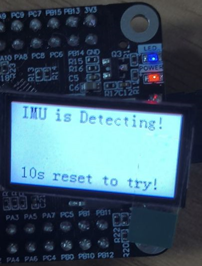
1.When it is detected that the IMU is not online, please press the reset key and power off to restart. The effect is as shown in the figure:
2.When the IMU is detected online and communicated, the LCD screen will display the accelerometer data, as shown in the figure:
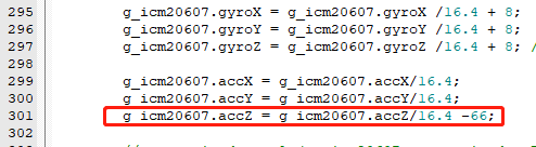
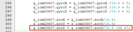
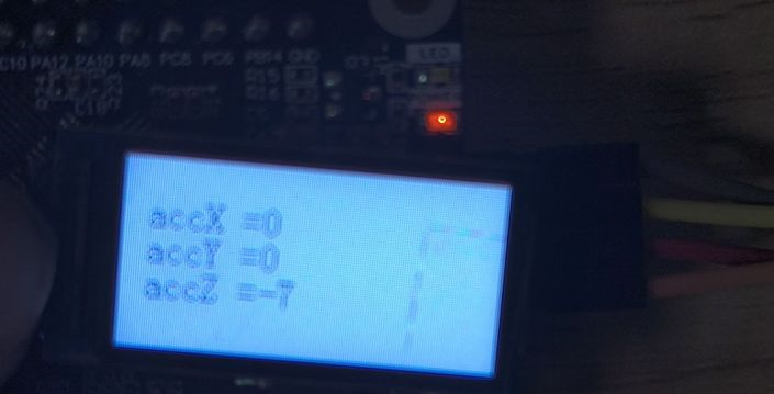 Note: If you see gyroscope or accelerometer and the prohibited data is not 0, please enter bsp in the project file_ In icm20607. c, modify (295-301). No line represents the x, y, and z values of each range meter. For example, the Z axis of the accelerometer in the above figure is - 7. Then add "+7" in line 301 and download the program again. This is mainly because each board is not welded well. The modification is shown in the figure
Before modification:
Note: If you see gyroscope or accelerometer and the prohibited data is not 0, please enter bsp in the project file_ In icm20607. c, modify (295-301). No line represents the x, y, and z values of each range meter. For example, the Z axis of the accelerometer in the above figure is - 7. Then add "+7" in line 301 and download the program again. This is mainly because each board is not welded well. The modification is shown in the figure
Before modification:
 After change:
3.However, when the IMU moves, the data will change constantly and be displayed on the LCD screen.